Service Telephone
+86-17773308230
DT16Y Subway Track Laying Vehicle
update time:2024/10/9 15:35:25
1. Structure Introduction
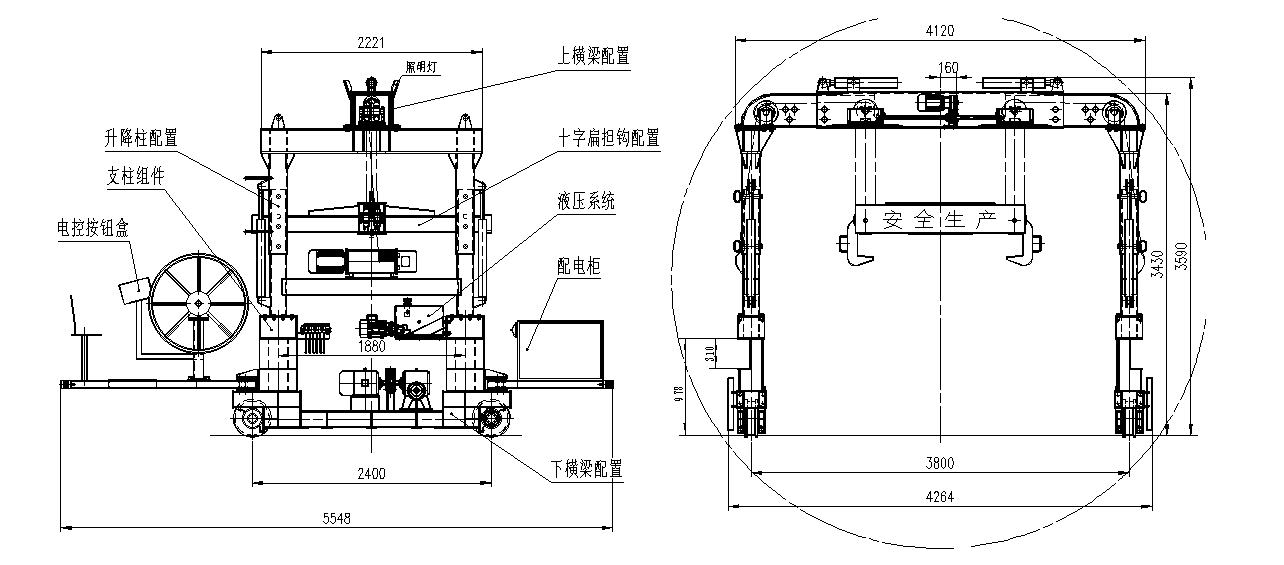
DT16Y subway track laying vehicle is designed and manufactured according to GB/T14406-93 "General gantry crane", GB5905-86 "Lifting test specifications and procedures" and related standards. It is mainly composed of steel structure, running mechanism, double electric hoist, lifting rail pole, cable drum, hydraulic part, electrical part and braking part. It is suitable for subway track laying, lifting and pouring concrete, and lifting track panels.

1.1 The steel structure adopts a completely symmetrical layout structure of building block splicing. The main crossbeam and lifting column are equipped with equidistant bolt holes and high-strength bolts. It is convenient for transfer and transportation, and the track laying vehicles can be assembled into different track gauges to meet the requirements of different construction conditions.
1.2 The running mechanism adopts a two-wheel drive mode with chain drive. The traveling speed is controlled by a three-speed adjustable frequency knob and can be adjusted between 5~25 m/min.
1.3 The lifting device adopts an electric hoist, and the upper crossbeam and cross pole beam are both equipped with a pulley block inside. The lifting speed of the electric hoist is 2.6 m/min.
1.4 Equipped with manual cable retractable drum and three-phase four-wire power transmission circuit.
1.5 The upper crossbeam is equipped with a transverse movement mechanism, which is driven by a motor gear and screw. It can achieve 180mm lateral movement to the left and right.
1.6 Electrical Parts
1.6.1 Two running motors, model Y3-160M1-8, with a rated power of 4 kW. To control the running speed, a frequency converter is adopted. Install 2 electric hoists, distributed on both sides, with power-off braking. Three speed variable frequency speed regulation.
1.6.2 All actions of the track laying vehicle are manually operated. Install two motors of the same type to drive the track laying vehicle, and both motors operate together. The left and right track panel hooks can be operated individually or in linkage; The lifting hoist of the hook itself is equipped with a broken fire limiter. When the steel wire rope reaches the top limit position, it can stop the hook and can only start the winch in reverse. Always pay attention to whether the limit and winch fire breaker are working.
1.7 Hydraulic Parts
The lifting mechanism and transverse movement mechanism of the subway track laying vehicle are controlled by a hydraulic system, and the main control valve adopts a multi-way reversing valve with mid-position unloading. The multi-way valve handle controls the lifting mechanism and the lateral movement mechanism respectively, and can be actuated by a single cylinder. The multi-way valve handle controls the lifting mechanism and the lateral movement mechanism respectively, and can be actuated by a single cylinder.
System Rated Pressure | 12Mpa |
| Rated Flow Rate | 11.3 L/min |
2. Main Performance Parameters
Lifting Capacity | 16 t |
Maximum Lifting Height | 2450 mm When The Track Gauge is 3800mm |
2750 mm When The Track Gauge is 3000mm | |
The Lifting Speed of The Electric Hoist | 2.6m/min |
Travel Speed | 5~ 25 m/min |
Maximum Climbing Ability | 35‰ |
Minimum Curve Radius to Pass | R=300m |
Span | 3000mm/3100mm/3200mm/3800mm/ 1435mm |
Wheelbase | 2400mm |
Dimensions | Length × Width × Height (Working State) |
| 5548× 4264× 3590 mm When The Track Gauge is 3800mm | |
Internal Clearance Size | Maximum Width 3000mm |
| 3380mm When The Track Gauge is 3000mm | |
| 3080mm when the track gauge is 3800mm | |
Horizontal Displacement Distance | Maximum ± 180 mm |
Total Weight | About 6 Tons |